|
|
|
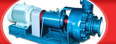
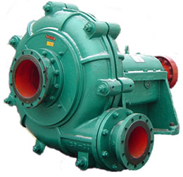
Multi-purpose Sludge Pump |
|
Product Introduction: |
Overview
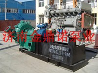
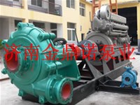
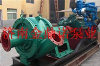
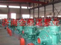
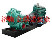
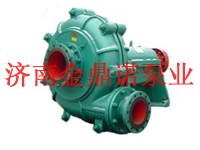
The multi-purpose sludge pump is single-stage single-suction centrifugal pump, and comprises several series and various specifications such as 500mm, 450mm, 400mm, 350mm, 300mm, 250mm, 200mm,150mm and so on according to outlet diameter. The pump is innovative in hydraulic design and structural design, and adopts the overflowing part cast by strong abrasion-resistant high chromium wear-resistant alloy, so the pump has the characteristics of high efficiency, energy conservation, wear resistance, reliable operation and so on. The blade number of the impeller of the pump can be changed according to different working conditions; and the pump is suitable for conveying strong-abrasion mortar, tailing slurry, slag and so on containing big and small solid particles. The maximum mixture concentration of conveyed powdery is up to 60 percent. Therefore, the pump is ideal sand pumping and conveying equipment and users can select single machine or multiple serially-connected machines to achieve the aim of long-distance conveying according to actual working conditions. The pump is widely applied to sand pumping from river channels and reservoirs, exploiting seashore, conveying electric fly ash and conveying tails in the metallurgical industry, etc.
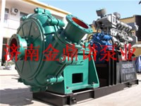
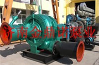
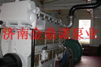
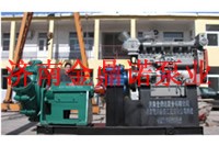
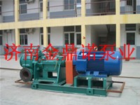
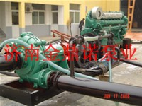
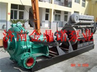
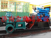
The pump can be equipped with different diesel engine unit, generator system and big or small pumps of different models according to different user’s requirements.
Structural Property
1、The pump body adopts a two-layer metal structure with an inner layer and an outer layer; the pump shell is vertically opened in the middle; and the water outlets are rotationally installed at 45 degree intervals.
2、The proper shaft seal can be selected such as auxiliary impeller shaft seal, packing shaft seal and mechanical seal according to different working conditions.
3、The pump adopts closed impeller, so the pump has good wear resistance and high pump efficiency.
4、The pump can convey mixture containing few big particles through adjusting the blade number and the impeller diameter.
NSStructural Drawing of NS Sludge Pump
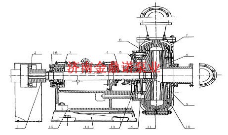
1、Shaft Joint 2、Shaft 3、.Bearing Housing 4、.Disassembly Ring 5、Auxiliary Impeller 6、Back Guard Plate 7、Worm Shell 8、Impelle 9、Front Guard Plate 10、Front Pump Shell 11、Back Pump Shell 12、Packing Box 13、Water-Sealing Ring 14、.Pedestal 15、Bracket 16、Adjusting Screw
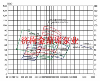
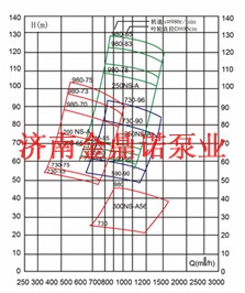
Parameters and Model Spectrum
|
Model |
Allowable Mating Maximum Power
(kw) |
Clear Water Performance |
The Maximum Particle Size Passed Discontinuously
(mm) |
Pump weight
(kg) |
|
Flow Rate Q
(㎡/h) |
Pump Lift
(m) |
Speed
(r/min) |
Peak Efficiency
(%) |
Net Positive Suction Head
(m) |
|
500NS-I-A140 |
1200 |
3750-7960 |
49-55.2 |
200-490 |
82 |
5-10 |
120 |
19100 |
|
450NS-I-A140 |
1200 |
3310-6610 |
52-57 |
200-490 |
85 |
5-10 |
120 |
18864 |
|
400NS-I-A125 |
1200 |
2520-5040 |
48-66 |
200-500 |
80 |
4.5-9 |
110 |
14432 |
|
350NS-I-F100 |
560 |
526-2339 |
14.9-62.8 |
300-590 |
77.6 |
4.4 |
96 |
5465 |
|
300NS-I-A100 |
450 |
464-1826 |
15.3-65.2 |
300-590 |
81.1 |
3.0 |
88 |
5265 |
|
300NS-I-A95 |
400 |
441-1735 |
13.8-58.8 |
300-590 |
78.1 |
3.0 |
88 |
5220 |
|
300NS-I-A90 |
560 |
505-1844 |
21.2-79.9 |
400-730 |
82.8 |
3.9 |
85 |
5005 |
|
300NS-I-A85 |
450 |
477-1742 |
18.9-71.3 |
400-730 |
79.8 |
3.8 |
85 |
4965 |
|
300NS-I-A70 |
630 |
635-2333 |
16.0-76.8 |
490-980 |
80.4 |
3.9 |
92 |
3560 |
|
300NS-I-A65 |
500 |
589-2166 |
13.8-66.2 |
490-980 |
77.4 |
3.7 |
92 |
3531 |
|
300NS-I-A56 |
250 |
395-1568 |
9.7-46.0 |
490-980 |
80.9 |
3.5 |
96 |
3030 |
|
250NS-I-A103 |
560 |
402-1573 |
29.7-110.5 |
400-730 |
74.5 |
2.8 |
69 |
5085 |
|
250NS-I-A96 |
560 |
403-1466 |
25.4-93.7 |
400-730 |
77.8 |
3.5 |
69 |
5200 |
|
250NS-I-A90 |
450 |
378-1374 |
22.3-82.4 |
400-730 |
73.8 |
3.4 |
69 |
5035 |
|
250NS-I-A85 |
800 |
376-1504 |
30.1-128.7 |
490-980 |
76.5 |
3.5 |
96 |
4530 |
|
250NS-I-A83 |
800 |
367-1469 |
28.7-122.7 |
490-980 |
75.5 |
3.5 |
76 |
4514 |
|
250NS-I-A80 |
710 |
354-1416 |
26.7-114.0 |
490-980 |
73.5 |
3.4 |
76 |
4490 |
|
250NS-I-A78 |
630 |
345-1380 |
25.4-108.4 |
490-980 |
71.5 |
3.2 |
76 |
4474 |
|
250NS-I-A75 |
560 |
300-1480 |
20.8-97.5 |
490-980 |
77.5 |
3.0 |
72 |
3480 |
|
250NS-I-A73 |
500 |
292-1441 |
19.7-92.4 |
490-980 |
76.5 |
3.0 |
72 |
3466 |
|
250NS-I-A70 |
450 |
280-1381 |
18.1-84.9 |
490-980 |
74.5 |
2.9 |
72 |
3446 |
|
250NS-I-A68 |
450 |
272-1342 |
17.1-80.1 |
490-980 |
73.5 |
2.7 |
72 |
3432 |
|
250NS-I-A65 |
315 |
299-1249 |
15.4-71.0 |
490-980 |
76.9 |
3.0 |
72 |
3020 |
|
250NS-I-A63 |
315 |
290-1211 |
14.4-66.7 |
490-980 |
75.9 |
3.0 |
72 |
3008 |
|
250NS-I-A60 |
280 |
276-1153 |
13.1-60.5 |
490-980 |
73.9 |
2.8 |
72 |
2991 |
|
200NS-I-A85 |
560 |
221-907 |
32.0-133.7 |
490-980 |
70.5 |
2.8 |
54 |
4110 |
|
200NS-I-A75 |
355 |
225-900 |
22.8-102.9 |
490-980 |
74.1 |
3.0 |
56 |
3070 |
|
200NS-I-A73 |
355 |
219-876 |
21.6-97.5 |
490-980 |
73.1 |
3.0 |
56 |
3056 |
|
200NS-I-A70 |
315 |
205-976 |
19.4-86.4 |
490-980 |
75.6 |
2.8 |
56 |
2465 |
|
200NS-I-A68 |
315 |
199-948 |
18.3-81.5 |
490-980 |
74.6 |
2.8 |
56 |
2453 |
|
200NS-I-A65 |
250 |
235-950 |
16.4-72.0 |
490-980 |
79.6 |
2.5 |
62 |
2323 |
|
200NS-I-A63 |
250 |
228-921 |
15.4-67.6 |
490-980 |
78.6 |
2.5 |
62 |
2311 |
|
200NS-I-A60 |
185 |
218-870 |
13.9-62.0 |
490-980 |
83.5 |
2.5 |
62 |
2223 |
|
200NS-I-A58 |
185 |
211-841 |
13.0-57.9 |
490-980 |
82.5 |
2.5 |
62 |
2214 |
|
200NS-I-A50 |
185 |
180-648 |
11-34.4 |
490-980 |
82.7 |
2.5 |
55 |
2013 |
|
150NS-I-A71 |
220 |
142-552 |
21.8-93.8 |
490-980 |
69.8 |
2.4 |
48 |
2263 |
|
150NS-I-A70 |
185 |
93-401 |
20.0-91.2 |
490-980 |
62.3 |
2.0 |
37 |
2245 |
|
150NS-I-A65 |
200 |
150-600 |
17.4-75.7 |
490-980 |
70.8 |
2.5 |
48 |
2223 |
|
150NS-I-A63 |
185 |
146-582 |
16.3-71.1 |
490-980 |
69.8 |
2.5 |
48 |
2211 |
|
150NS-I-A60 |
160 |
135-550 |
14.7-63.5 |
490-980 |
75.9 |
2.5 |
48 |
2203 |
|
150NS-I-A58 |
132 |
131-532 |
13.7-59.3 |
490-980 |
74.9 |
2.5 |
48 |
2033 |
|
150NS-I-C58 |
160 |
134-596 |
12.8-61.0 |
490-980 |
69.1 |
2.0 |
75 |
2063 |
|
150NS-I-A57 |
110 |
95-427 |
13.2-56.3 |
490-980 |
67.8 |
1.8 |
32 |
2023 |
|
150NS-I-A55 |
110 |
124-504 |
12.3-53.4 |
490-980 |
72.9 |
2.3 |
48 |
2019 |
|
150NS-I-A50 |
75 |
115-460 |
9.5-43.1 |
490-980 |
76.8 |
2.5 |
48 |
1735 |
|
150NS-I-A48 |
75 |
111-442 |
8.7-39.7 |
490-980 |
75.8 |
2.5 |
48 |
1728 |
|
150NS-I-C42 |
132 |
142-550 |
12.1-62.8 |
700-1480 |
77.1 |
2.2 |
69 |
1605 |
|
100NS-I-A60 |
315 |
103-380 |
55-176 |
700-1480 |
55.1 |
3.0 |
30 |
1575 |
|
100NS-I-A50 |
160 |
85-360 |
20.5-100.2 |
700-1480 |
69.6 |
2.5 |
34 |
1475 |
|
100NS-I-A46 |
132 |
79-331 |
17.3-84.8 |
700-1480 |
67.6 |
2.3 |
34 |
1461 |
|
100NS-I-A42 |
90 |
66-275 |
14.7-70.8 |
700-1480 |
71.0 |
2.5 |
35 |
1075 |
|
100NS-I-B42 |
90 |
83-365 |
12.7-66.8 |
700-1480 |
71.6 |
2.5 |
40 |
1085 |
|
100NS-I-A39 |
75 |
61-255 |
12.6-61.0 |
700-1480 |
69.0 |
2.4 |
35 |
1064 |
|
100NS-I-A36 |
55 |
61-245 |
9.7-49.5 |
700-1480 |
71.6 |
2.0 |
32 |
1010 |
|
100NS-I-A33 |
45 |
56-225 |
8.2-41.6 |
700-1480 |
69.6 |
1.8 |
32 |
1003 |
|
80NS-I-A52 |
160 |
51-242 |
22.1-109.8 |
700-1480 |
56.3 |
2.1 |
21 |
1456 |
|
80NS-I-A42 |
75 |
61-204 |
14.4-70.4 |
700-1480 |
66.7 |
2.5 |
24 |
1053 |
|
80NS-I-A39 |
55 |
57-189 |
12.4-60.7 |
700-1480 |
64.7 |
2.4 |
24 |
1042 |
|
80NS-I-A36 |
45 |
46-190 |
9.6-51.4 |
700-1480 |
67.7 |
2.5 |
24 |
980 |
|
80NS-I-A33 |
37 |
43-174 |
8.0-43.2 |
700-1480 |
65.7 |
2.3 |
24 |
973 |
Details
NS Sludge Pump Model Spectrum
Application Instruction
1、Starting: please check the whole unit in the following steps before starting:
⑴ The pump should be placed on a firm foundation to bear the whole weight of the pump and eliminate vibration, and all the stone bolts should be screwed tightly.
⑵ Valves of the pipes should have their own supports which shall be firm. The pump flange is provided with seal points, the connecting bolts should not be screwed too tightly, so as to avoid damaging the seal points.
⑶ The shaft is rotated by hands in the rotation direction of the pump; when the shaft rotates, there should not be friction; otherwise the clearance of the impeller should be adjusted.
⑷ The rotation direction of the motor should be checked to ensure that the pump rotates in the arrow direction marked in the pump body. The reverse rotation should be absolutely prohibited.
⑸ For direct connection drive, the shaft of pump should be centered with the shaft of motor accurately; for belt drive, the shaft of pump should be parallel to the shaft of motor, and the groove wheel should be adjusted to be vertical to the groove belt, so as not to cause vibration and abrasion.
⑹Gland seal should be checked: check water quantity and pressure of the shaft seal, adjust the compression screws on the gland cover, adjust the tight degree of the packing and adjust the gland seal water. It is better that the leakage from the gland cover is drop by drop, for if the packing is too tight, the shaft housing is easy to become hot and the power consumption is high, otherwise, the liquid leakage is too much. The pressure of the gland seal should be 35KPa higher than the outlet pressure of the pump generally, and the quantity of the gland seal should be between 0.15 and 2.1 L/S according to different models generally. The pump provided with the mechanical seal should be supplied with the gland seal water before starting.
2、Operating:
⑴ The pressure and flow rate of the gland seal water should be checked regularly in operation to adjust the gland cover or replace the packing, so as to ensure that there is always a small quantity of clear water passing through the shaft.
⑵ The operating condition of the bearing assembly should be regularly checked; and NO.20 or 30 lubricating oil should be injected in the axis body and cooling water is connected on the hose connector (no need of cooling water if below 18.5kw) before starting. The lubricating oil of the bearing should be clean in right amount, and added and replaced regularly.
⑶ The pump efficiency is reduced when the clearance between the impeller and the guard plate is increased, so the impeller should be adjusted forwards in time to keep certain clearance and ensure high-efficiency operation of the pump. When the pump is worn and cannot meet system demands, the wearing parts should be replaced; the pump should be overhauled regularly to evaluate the service life of the wearing parts, so as to avoid serious results to the system due to failed bearing parts.
3、Stopping the Pump:
Before stopping the pump, the pump should pump and send clear water for a while possibly, so as to clean slurry flowing through the pump; and then the pump, the gate, the gland seal water and the cooling water of the bearing body should be closed in turn.
Maintenance
Routine maintenance should be performed to ensure safe operation and long service life of the pump. The following respects should be noticed in the maintenance:
1、Maintenance of the Gland Seal:
The pressure and quantity of the gland seal should be checked regularly to ensure that a small quantity of clear water always flows along the shaft; the gland cover should be adjusted regularly; and the packing should be checked and replaced regularly. The pressure and quantity of the gland seal should accord with the above mentioned (gland seal check) requirements. For pump provided with the mechanical seal and not used for a long time, mechanical seal parts should be filled with N46 machine oil, so as to prevent rustiness of the mechanical seal parts and failure of the inside rubber parts.
2、 Adjustment of the Impeller:
To ensure high-efficiency operation of the pump, the clearance between the impeller and the front guard plate should be adjusted in time. When the clearance of the impeller is adjusted, the pump is stopped firstly, the bolts pressing the bearing assembly tightly are loosened, the nuts on the adjusting bolts are screwed to make the bearing assembly move forward; simultaneously, the shaft is rotated by hands in the rotation direction of the pump until the impeller rubs the front guard plate, the nuts screwed tightly before are loosened by half circle and then screwed tightly, so as to make the bearing assembly move backward; at this time, the clearance between the impeller and the front guard plate is between 0.5 and 1mm. After the adjustment, it should recheck whether the rotation of the impeller is normal, and whether the hold-down bolts of the bearing assembly are screwed tightly before restarting, and then the pump can be started.
3、Lubrication of the Bearing:
The bearing assembly has longer running life if the bearing assembly is correctly assembled, the lubricating oil is added in right amount and the maintenance is performed in time. Maintenance personnel should periodically overhaul the bearing assembly, check the conditions of the bearing assembly and the lubricating oil, and periodically add or replace the lubricating oil in the operation. The time interval and injection amount of the lubricating oil are related with many factors such as rotation of the pump, specification of the bearing, continuous working time, stopping and starting times of the pump, ambient environment and operating temperature, so the maintenance personnel should gradually gather experience to reasonably add the lubricating oil in time.
4、4. For spare pump, its shaft should be rotated 1/4 circle each week, so that the shaft bears even static load and external vibration.
Error Causes and Countermeasures
|
Faults |
Causes |
Solutions |
|
Incapability of sucking water of the pump |
Air leakage of the suction pipe or the packing position, damage of the impeller, blockage of the suction pipe, unable discharging of the air in the pump, air blockage of the suction pipe, unable realization of water sealing on water outlets of the pump |
Plugging the air leakage parts, replacing the impeller, removing the blockage, checking the suction force of the emptying device, moving the suction pipe to discharge the air, lifting or lowering the hoses on the water outlets |
|
Overhigh power of the shaft |
Over tight pressing of the packing, heat emission of the packing, friction in the pump, damage of the bearing, large flow rate of the pump, high speed, large medium proportion, no centration of the axes |
Loosening the bolts of the gland cover, adjusting the clearance of the impeller, replacing the bearing, adjusting the diameter of the water outlet pipe, lowering the speed, reducing medium concentration, adjusting the axes |
|
Bearing running hot |
Excessive or insufficient lubricating oil of bearing, impurities in the lubricating oil, damage of the bearing |
Adding the lubricating oil according to the operation instruction, replacing the lubricating oil, replacing the bearing |
|
Short service life of the bearing |
Disalignment of power output shaft and the shaft of pump, unbalance of the impeller, foreign matters in the bearing, improper amount of the lubricating oil |
Adjusting the concentricity of the power output shaft and the shaft of pump, replacing the impeller, cleaning the bearing or replacing the bearing |
|
Serious leakage on the seals |
Serious wear of the packing, serious wear of the shaft housing, damage of the seals or the auxiliary impeller |
Replacing the packing, replacing the bearing, replacing the seals or the auxiliary impeller |
|
Large vibration and noise of the pump |
Damage of the bearing, unbalance of the impeller, air sucked in the suction pipe, uneven flow rate, empty pumping of the pump |
Replacing the bearing, replacing the impeller, removing the air, clearing the blockage |
Different Configurations in Different Application Environments
|
|
|
 |
|